This section describes some ideas how to put the sensor station in practice. I hope this section will grow so if you have a awesome idea/solution, please let me know !
Make sure your solderjumper settings are correct. See using for more info. If not set correct the microcontroller is not able to do correct measurements!
App Idea 1:
(Battery pack) voltage
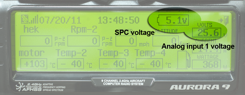
Out of the box, the Aurora 9 shows the voltage on the SPC (Supplementary Power Connection) connector of the Optima 7/9 receiver. When the SPC
connector is ‘jumpered’ (default) the optima 7/9 is powered by its ‘channels’ and the Aurora 9 will show voltage levels of around 5 Volt.
If you power the Optima using the SPC, the Aurora 9 shows the voltage of the SPC power source (see manual for more information).
A better and a more practical example is to power the Optima 7/9 by a ESC/BEC. Then the receiver voltage remains constant (stabilized to 5 Volts) even
if the system battery voltage (your lipo pack) drops (a sign of an empty battery pack!). This way the receiver is always powered including all
connected servos keeping your plane controllable.
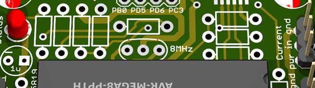
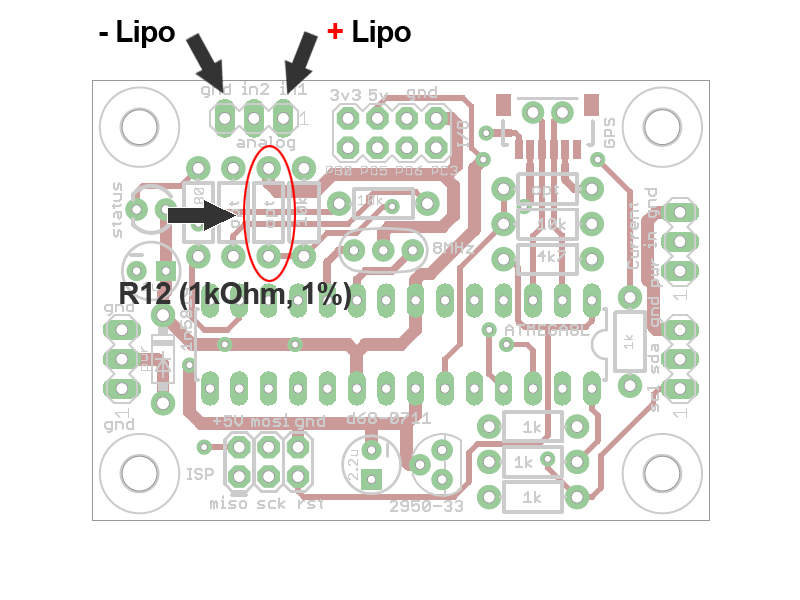
With the sensor station you can monitor both voltages simultaneously. You only have to mount R12 (1kOhm-1%) and connect 'the voltage to be measured'
input 1 (marked as in1 on the PCB) to the + (red) terminal of your battery pack (assuming all grounds are connected, check your ESC/BEC).
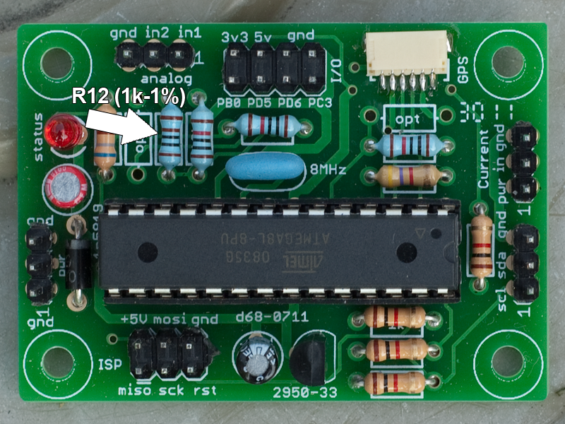
R12 (see schematic) - color code: brown-black-black-brown (brown) - is a 1kOhm-1% resistor marked as 'opt' on the board, image below. You have 2 in the DIY kit.
The Aurora 9 will show both voltages in 'pilotview' On both values you can set alarms.
Warning: make sure the inputs are not reversed! This may damage the sensorboard and/or microcontroller !
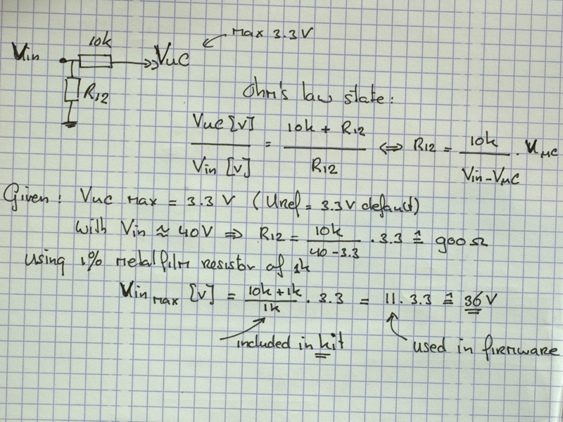
Default analog input 1 has an input voltage range from 0 - 35 Volts. See the math in the above images if you need other max. ranges.
App Idea 2:
Electrical current and power consumption
Your battery pack is specified by a capacity, e.g. 2200mAh, (theoreticly) meaning you can draw 2200 mA = 2.2 Amps for one hour, 4.4 Amps for half an hour and so on. (Your battery pack will wear meaning capacity will become lower after some time). Knowing how much current your plain drains is a good indication for the remaining fly-time left.
Another good reason knowing the amount of current drawn is ‘current versus efficiency’. Propeller choices influence the efficiency of the propulsion meaning that with the right prop less power (=current) is needed to achieve the same flying characteristic as with a less effective prop. And this means that with the right propeller you can extend your fly-time.
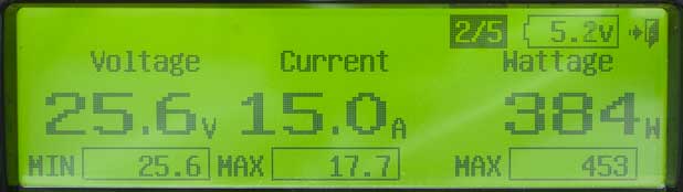
Power consumption (in Watts) equals Voltage x Amps. With a current sensor connected the sensor station the Aurora 9 will show all the important
values: System voltage in Volts, total current flow in Amps and calculated power consumption in Watts. (So you can start experimenting with different
props).
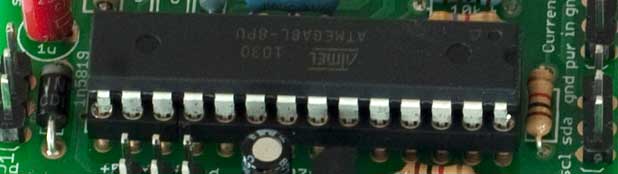
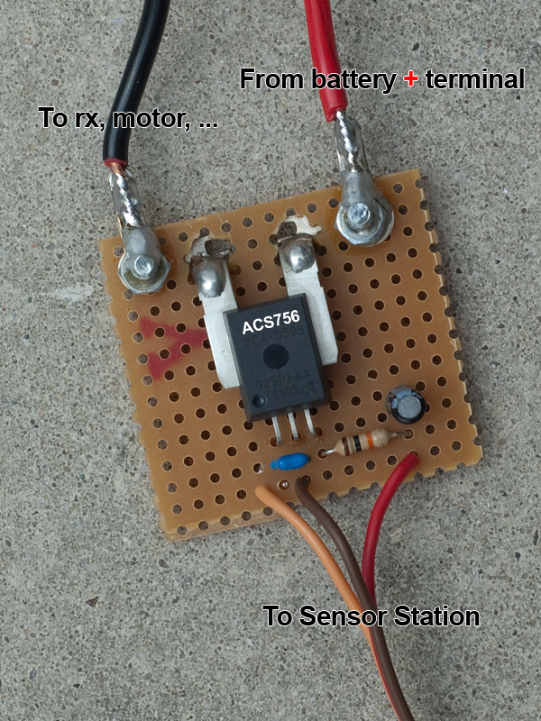
The simplest current sensor to interface is the the cheap, but accurate, ACS765 chip. This chip can be used if your system draws not more than
approximately 30 Amps. You can purchase ACS765 chips here, here here. Interfacing ACS765 is really easy, see images. R8 needs to be 10k.
The second choice is using the 'AttoPilot Voltage and Current Sense Breakout board' from sparkfun. I have not tried it myself (waiting for the board), I will keep you informed
There a lot more current sensor options. Click here and here. Interface your own, all software is opensource! If you found some clever solution, please let me know. The default firmware assumes the use of the cheap ACS765 chip. To have accurate readings the default firmware uses the following procedure: At power-up (after a reset) the ACS765 chip is sampled. The current measured is the so-called ‘zero value’. All measurement from this point on (until a new power cycle) are relative to the ‘zero value’.
App Idea 3:
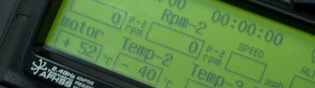
Temperature monitoring
There are many cheap and accurate temperature sensors available today e.g. the LM335 (-40°C – 100°C). This (semiconductor) device has a typical uncalibrated temperature error of around 3°C, well enough for RC applications. Interfacing a LM335 to the sensor board is easy: add a few resistors, add small piece of shrink tube and connect the LM335 to the optional I/O connectors as shown in the following images.
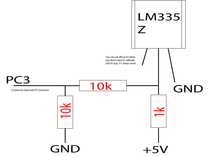

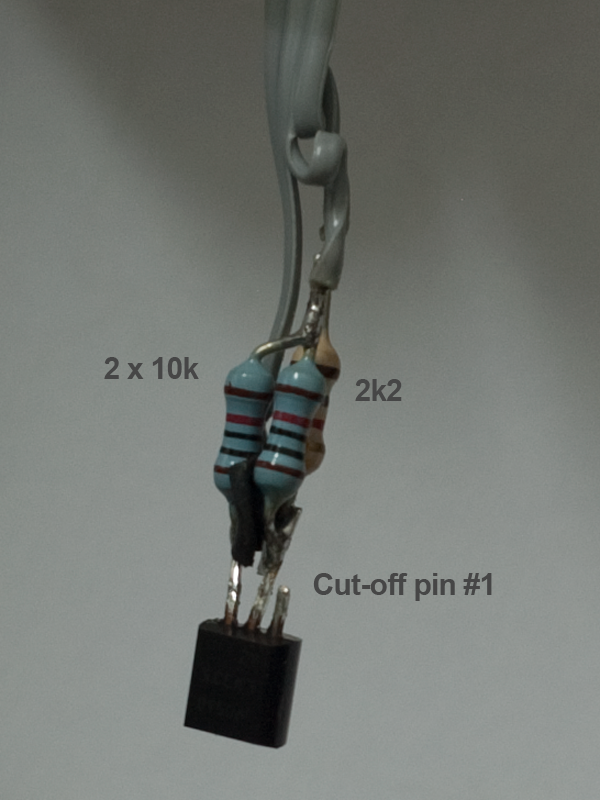
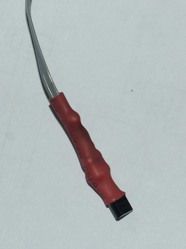
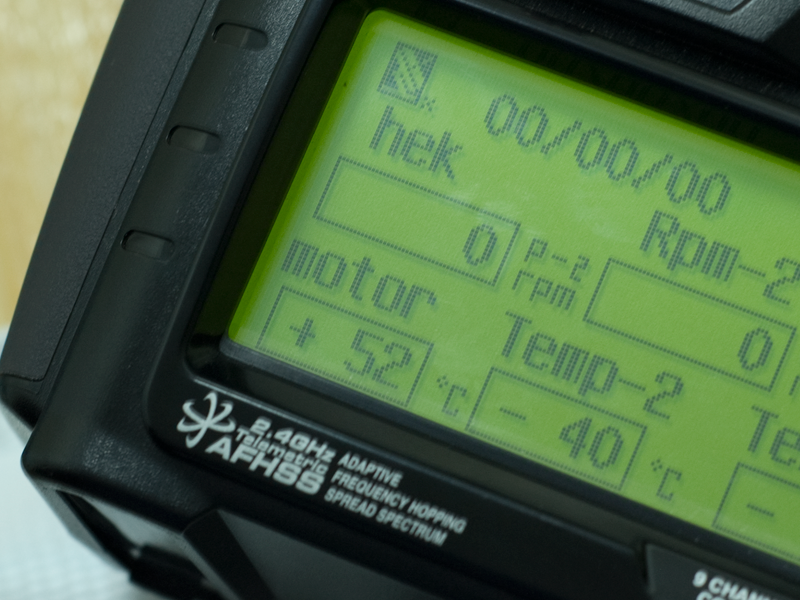
Glue / mount the temperature sensor to the out-runner, battery pack or ESC and always be informed about their temperature. You can add another temperature sensor to the voltage 2 input (use the 5 Volt from the optional I/O connector), this way you can monitor 2 temperatures simultaneously.
App Idea 4:
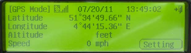
Global Positioning System (GPS)
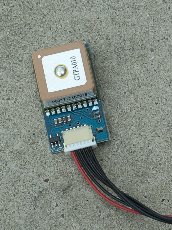
The sensor station is compatible with all GPS devices that outputs NMEA RMC and/or GGA sequences, 99% of all GPS devices do. One cheap but very good and small GPS is the MediaTek MT3329 available from diydrones.com. Buy the one with the Adapter Basic board. Included with the Adapter Basic board is a cable that connects directly to the sensor board. Just plug it in and wait till the blue led stops flashing meaning your GPS has a position lock. After that the Aurora 9 will display your current position, direction, altitude and speed. Remark that for accurate direction info you have to move first, GPS devices do not include a compass!)

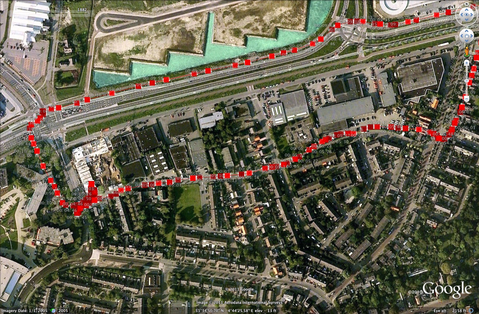
Connected to Hitec HPP-22 PC programmer all sensor station data can be logged. The above image shows, in Google Earth, the tracklog of a (system test)car drive with the system. Here the Google Earth file, here the file created by the (not so cool) HPP-22 programmer.